

Picking the right Physical Vapor Deposition coating in 2026 isn't just about comparing colors, hardness, or prices. Honestly, it’s way more complicated than that. Every application has its own set of challenges—whether it's dealing with friction, heat, corrosion, load requirements, or how easy it is to clean. A coating that works perfectly on cutting tools might totally flop when used on decorative hardware or medical parts.
In this guide, we’ll take a look at some of the top PVD coatings like Titanium Nitride, Chromium Nitride, Aluminum Titanium Nitride, Zirconium Nitride, and Diamond-Like Carbon. Sure, they can all look pretty similar—golden, silver, blue, or dark finishes—but their performance profiles are worlds apart. Titanium Nitride, for example, is still a go-to for wear resistance and general tools. Aluminum Titanium Nitride is great for intense cutting jobs because it forms a protective aluminum-rich layer when things heat up. And then there's Diamond-Like Carbon—it's known for reducing friction, but you gotta be careful with prep work and application since those factors can really impact how well it performs.
When you're actually choosing a coating, it’s all about the data. Don’t just rely on what the supplier says—ask them for specifics like coating thickness, hardness, how well it sticks, the deposition temperature, and testing methods. Also, it’s a good idea to get samples that match your actual substrate and the conditions they’ll be used in. Little things like a sharp edge, a polished surface, or even a poorly cleaned recess can totally change the outcome.
Remember, there’s no one-size-fits-all answer. No coating is perfect for every situation—try as you might, that’s often just not the case.
And besides the performance itself, don’t forget about factors like cost, maintenance, how it holds up against environmental exposure, and whether it’s consistent from batch to batch. While published data is helpful, independent testing can really shed more light. Keep in mind, some performance claims depend heavily on how the equipment is set up and how well everything has been prepared—that’s an area to pay attention to. Ultimately, the best PVD coating isn’t necessarily the hardest or fanciest; it’s the one that provides reliable performance under real-world conditions.
Hope this helps clear things up a bit – choosing the right coating can be tricky, but knowing what to look for makes a big difference.

PVD coating fundamentals begin with a practical range: 1–5 μm films deposited in vacuum. Solid material becomes vapor through evaporation, sputtering, or cathodic arc processes. The vapor then condenses on a prepared substrate.
Working pressures commonly remain near 0.1–1 Pa, while the chamber reaches a much lower base pressure. ASM Handbook Volume 5A identifies substrate cleaning, ion bombardment, temperature, and bias voltage as major adhesion controls. Thickness alone does not guarantee performance. It can mislead.
For cutting tools, titanium aluminum nitride and chromium nitride support wear and heat resistance. Titanium nitride remains useful where visual inspection and moderate wear protection matter. Chromium-based films can help reduce oxidation and sliding damage.
The suitable choice depends on load, temperature, lubrication, and substrate hardness. A 2024 MarketsandMarkets assessment valued the global PVD market at approximately USD 22 billion and projected continued growth through 2029. That figure reflects broad demand, not guaranteed coating quality.
In production, complex edges and deep holes still receive uneven coverage. Engineers should verify thickness with calotest, microscopy, or X-ray fluorescence testing.
The overlooked detail is pretreatment. Poor cleaning can ruin an otherwise excellent 3 μm film.
2026 Best Physical Vapor Deposition Coating Types?
Choosing a PVD coating starts with the working surface, not a trend list. In shop trials, TiN remains useful for general wear. Its gold color also makes coverage defects easy to spot. CrN suits damp environments and sliding parts because it resists oxidation better than many basic nitride layers. TiAlN and AlTiN handle heat well during intermittent cutting, although performance depends on composition and temperature. Small chemistry changes matter.
DLC offers low friction on compatible substrates, especially where dry movement creates black dust or scuff marks. It is not a universal answer; poor adhesion can cause early flaking. Multilayers combine different functions, such as a tough base with a hard outer layer. Their interfaces may improve crack resistance when deposition control stays consistent. PVD should also be compared with Chemical Vapor Deposition Cvd when geometry, temperature, or coating thickness affects the decision.
Tips: Check hardness, adhesion, friction, and edge retention on the actual component. Measure the mating material too. A coating that survives laboratory testing may fail against a rough counterface. Request cross-section inspection and process records, not only a data sheet. Leave room for doubt. Tool geometry, cleaning, substrate hardness, and handling can outweigh the selected coating type. Run a small controlled batch before changing every part.
Choosing the best Physical Vapor Deposition coating in 2026 depends on the working environment, not only a headline number.
Hard coatings such as TiN, CrN, AlTiN, and multilayer systems can reach approximately 20–40 GPa hardness under controlled laboratory testing. That range supports cutting edges, forming tools, and wear-prone components.
However, hardness alone can mislead. Adhesion, toughness, friction, coating thickness, and substrate preparation often decide service life.
Oxidation resistance near 2,000°C requires careful interpretation. Most commercial PVD coatings do not continuously withstand 2,000°C in air. Specialized ceramic compositions may show exceptional short-term stability, but testing atmosphere and exposure time change the result dramatically. In practical trials, oxidation often begins earlier at sharp edges, pores, or damaged areas. My experience suggests that a coating surviving a brief furnace test may still fail during repeated thermal cycling. This is where technical reports need more honesty.
Tips: Ask for hardness, oxidation, adhesion, and thermal-cycle data from the same test method. Check whether values describe a coating, a coating system, or a bulk ceramic. Compare Chemical Vapor Deposition Types when temperatures exceed typical PVD limits. Use microscopy after testing; visible cracking can reveal more than one impressive figure. Slightly lower hardness may provide better toughness and longer performance. That trade-off deserves attention.
Deposition routes matter more than fashionable coating names. Cathodic arc produces a highly ionized plasma and strong adhesion. Its dense flux suits cutting tools and wear parts. However, macroparticles can leave visible droplets on polished surfaces. Careful filtering helps, but it can reduce deposition speed.
Magnetron sputtering offers smoother films and better coverage across complex components. It is often preferred for decorative, optical, and precision engineering applications. The process can be slower. HiPIMS increases metal-ion content through short, high-power pulses. This improves film density and substrate adhesion. The trade-off is real: power supplies, thermal control, and process tuning become more demanding. No route wins everywhere.
MarketsandMarkets reported steady growth in the PVD coating market, forecasting a compound annual growth rate of about 7% through the later 2020s. Grand View Research also identified tool manufacturing, automotive parts, and electronics as major demand areas in its 2024 market assessment. These figures support continued investment, not automatic technical success. A coating engineer should test hardness, friction, corrosion resistance, and edge geometry on the actual component. Plasma Chemical Vapor Deposition may suit temperature-sensitive designs, but it follows different chemistry and process limits. I would not select a route from a brochure alone. Small chamber differences can change the result.
2026 Best Physical Vapor Deposition Coating Types?
Choosing a PVD coating should begin with the application, not the coating chart. Cutting tools often need high hardness, heat resistance, and low friction. TiAlN or AlTiN can suit high-speed milling, especially when edge temperatures rise. For forming dies, CrN may offer useful wear resistance and smoother release during stamping. The answer is not always the hardest coating. A brittle layer can chip when the die flexes or receives impact.
Medical devices require a different decision. Coatings must support cleaning, corrosion resistance, and surface compatibility. Chromium-based layers or DLC may reduce friction on selected components, but substrate preparation remains critical. Electronics need thin, uniform films with controlled electrical behavior. PVD can support conductive, decorative, or barrier functions, depending on the metal and process settings. Engineers should also compare PVD with the Chemical Vapor Deposition Process when complex shapes or deeper coverage matter.
Tips: Match coating thickness to edge geometry. Check adhesion after cleaning and sterilization cycles. Test real cutting fluids, not only laboratory oils. For dies, inspect corners and draw radii under magnification. For electronics, measure sheet resistance across the full panel. Small variations matter. A practical trial should include temperature, load, and cleaning conditions from production. Some early choices will need revision; that is normal. Surface roughness, deposition temperature, and pretreatment can change performance more than expected.
Application-oriented comparison of common PVD coating families. Actual performance depends on substrate material, edge geometry, surface preparation, coating architecture, operating temperature, lubrication, and process parameters.
| PVD Coating Type | Typical Composition | Best-Matched Applications | Key Performance Advantages | Typical Working Temperature* | Typical Thickness | Substrate Compatibility | Main Limitations |
|---|---|---|---|---|---|---|---|
| TiN (Titanium Nitride) |
TiN ceramic coating with a characteristic gold color. | General-purpose cutting tools, forming tools, punches, dies, and decorative wear parts. | Good hardness, adhesive wear resistance, moderate oxidation resistance, and easy visual inspection. | Commonly suitable for continuous use up to approximately 500 °C, depending on conditions. | Approximately 1–5 µm | High-speed steel, cemented carbide, tool steel, stainless steel, and selected hardened steels. | Lower hot-hardness and oxidation resistance than Al-containing nitride coatings; less suitable for severe high-temperature cutting. |
| AlTiN / AlCrN | Aluminum-containing titanium nitride or chromium nitride; often deposited as multilayer or nanolayer structures. | Carbide cutting tools for dry, high-speed, and difficult-to-machine materials; hot-work tooling and high-load dies. | Strong thermal stability, high oxidation resistance, good hot hardness, and improved resistance to crater and flank wear. | Often selected for applications approaching approximately 800–1,100 °C at the cutting edge, depending on coating chemistry and atmosphere. | Approximately 1–5 µm | Cemented carbide, cermet, high-speed steel, and compatible hardened tool steels. | May be too brittle or thermally mismatched for poorly prepared substrates; not automatically optimal for low-temperature adhesive wear. |
| TiCN (Titanium Carbonitride) |
Carbon-modified titanium nitride with higher carbon content than TiN. | Cutting tools, punches, stamping dies, and abrasive forming applications requiring higher hardness than TiN. | Higher hardness and wear resistance than TiN; useful against abrasive and adhesive wear in moderate-temperature service. | Generally preferred below approximately 400–500 °C because oxidation resistance is lower than that of many Al-containing coatings. | Approximately 1–4 µm | High-speed steel, tool steel, cemented carbide, and selected cold-work die materials. | Limited high-temperature oxidation resistance; excessive thickness or sharp edges can increase chipping risk. |
| TiAlN / TiSiN | Titanium-aluminum nitride or silicon-containing nanocomposite nitride. | High-speed milling, drilling, hard machining, and cutting of stainless, hardened, and heat-resistant alloys. | High hot hardness, strong oxidation resistance, and good resistance to thermal cycling when properly engineered. | Often used for high-speed cutting environments with cutting-edge temperatures commonly above those tolerated by TiN. | Approximately 1–5 µm | Cemented carbide, cermet, and selected high-speed steel cutting substrates. | Performance is sensitive to coating design and cutting parameters; may not be ideal for interrupted cuts with severe impact loading. |
| CrN (Chromium Nitride) |
Chromium nitride, commonly deposited as a dense, low-friction wear coating. | Aluminum and copper forming tools, plastic molds, dies, corrosion-exposed tooling, and selected medical components. | Good corrosion resistance, low galling tendency, good adhesion on suitable substrates, and stable performance in humid environments. | Commonly used in moderate-temperature applications up to approximately 600–700 °C, subject to atmosphere and load. | Approximately 1–5 µm | Tool steels, stainless steels, nickel alloys, copper alloys, and some medical-grade metallic substrates. | Usually not the first choice for maximum abrasive wear resistance in high-speed cutting; surface preparation is critical for corrosion performance. |
| DLC (Diamond-Like Carbon) |
Hydrogenated or hydrogen-free carbon-based coatings containing significant sp3 bonding. | Medical instruments, precision sliding components, seals, automotive-style wear interfaces, and low-friction dies. | Very low friction, strong resistance to adhesive wear, and useful protection against fretting and material transfer. | Many DLC grades are best kept below approximately 200–350 °C; temperature limits vary substantially by hydrogen content and structure. | Approximately 0.5–3 µm | Stainless steel, cobalt-chromium alloys, titanium alloys, tool steels, ceramics, and selected polymers with compatible processes. | Can lose hardness or oxidize at elevated temperature; internal stress and adhesion must be controlled, especially on soft substrates. |
| ZrN (Zirconium Nitride) |
Zirconium nitride ceramic coating with a pale gold or brass-like appearance. | Medical and dental instruments, surgical components, decorative wear parts, and selected forming tools. | Good hardness, chemical stability, corrosion resistance, and biocompatibility potential when the complete coating system is properly qualified. | Commonly selected for moderate-temperature service, often below approximately 600 °C. | Approximately 1–4 µm | Stainless steel, titanium alloys, cobalt-chromium alloys, and other qualified metallic medical substrates. | Medical use requires process validation, cleanliness, sterilization compatibility, and regulatory qualification; not a substitute for surface passivation. |
| TiN / TiCN Medical-Grade Systems | TiN or TiCN top layers, often combined with adhesion or diffusion-barrier layers. | Surgical tools, orthopedic instrument surfaces, dental tools, and wear-resistant components requiring a hard ceramic surface. | High hardness, improved scratch and wear resistance, reduced metal-to-metal contact, and identifiable surface coloration. | Typically used in low-to-moderate temperature service; sterilization cycles must be evaluated for the full substrate and coating system. | Approximately 1–4 µm | Implant-grade titanium, stainless steel, cobalt-chromium alloys, and instrument-grade tool steels. | Coating safety cannot be inferred from composition alone; particle release, delamination, roughness, and sterilization durability require testing. |
| ITO (Indium Tin Oxide) |
Transparent conductive oxide, typically indium oxide doped with tin oxide. | Transparent electrodes for displays, touch sensors, photovoltaic devices, optical electronics, and transparent heaters. | Combines optical transparency with electrical conductivity; suitable for patterned thin-film electronic structures. | Deposition and post-treatment temperatures vary widely; temperature-sensitive substrates may require low-temperature processes. | Approximately 50–300 nm | Glass, selected polymers, silicon, and other substrates compatible with the deposition and annealing process. | Indium supply and cost considerations; conductivity and transparency vary with thickness, oxygen content, roughness, and annealing. |
| Al₂O₃ / TiO₂ Optical Layers | Aluminum oxide and titanium oxide dielectric layers, often used in multilayer optical stacks. | Optical filters, anti-reflection systems, laser optics, sensors, camera components, and protective electronic surfaces. | High optical design flexibility, electrical insulation, chemical stability, and improved surface protection when multilayer-engineered. | Thermal limits depend on substrate and stack design; many systems are intended for moderate-temperature optical service. | Approximately 50 nm–2 µm per layer or stack component | Glass, fused silica, sapphire, silicon, ceramics, and selected temperature-tolerant polymers. | Optical performance is highly sensitive to thickness uniformity, refractive-index control, surface defects, and environmental durability. |
| Cr / Cu / Ag Conductive Films | Metallic chromium, copper, silver, or adhesion-layer and conductive-layer combinations. | Electronic contacts, electromagnetic shielding, sensors, microelectronic interconnects, and thin-film conductive elements. | Low electrical resistance, controllable thickness, and compatibility with patterned thin-film manufacturing. | Service temperature depends on the metal, substrate, diffusion barriers, and encapsulation; oxidation and electromigration must be assessed. | Approximately 10 nm–2 µm | Glass, ceramics, silicon, polymers, flexible substrates, and plated or coated components with suitable adhesion layers. | Metal films may oxidize, diffuse, or agglomerate; adhesion, thermal expansion mismatch, and current-density limits are important. |
| Multilayer / Nanolayer PVD | Alternating layers such as TiN/AlTiN, CrN/AlCrN, or nitride-based nanocomposite architectures. | High-performance cutting tools, stamping dies, injection molds, aerospace tooling, and components exposed to combined wear modes. | Can balance hardness, toughness, oxidation resistance, residual stress, and crack deflection more effectively than a single layer. | Designed according to the selected layer chemistry; high-temperature capability may exceed conventional TiN when properly engineered. | Approximately 1–6 µm total | Cemented carbide, tool steel, high-speed steel, stainless steel, and other properly prepared engineering substrates. | Higher process complexity and cost; coating architecture must be matched to load type, edge preparation, temperature, and failure mode. |
Choosing a PVD coating in 2026 requires more than comparing hardness values. TiN offers a practical balance for moderate wear and temperatures up to roughly 500°C. CrN often suits corrosion-prone parts and sliding contact. AlTiN or AlCrN can protect cutting tools at higher temperatures, often near 800°C in controlled applications. DLC coatings reduce friction, but their performance depends strongly on substrate preparation and counterface material.
Wear life should come from representative testing, not a brochure claim. Compare mass loss, friction, surface damage, and operating hours under real loads. Adhesion testing matters too. Scratch-test critical loads can reveal weak interfaces, but results vary with coating thickness and test equipment. A clean, properly hardened substrate often matters as much as coating selection. Small details matter.
Temperature data needs caution. The listed maximum temperature may describe oxidation resistance, not continuous service. Thermal cycling, impact, and lubricant exposure can reduce life sharply.
Cost should include cleaning, masking, inspection, and replacement downtime. A lower-cost coating may become expensive after two premature failures. Still, expensive coatings are not automatically better.
I would request sample testing and review failure evidence before approving production. The difficult part is admitting that laboratory results may not predict every field condition. Based on experience, the best choice is usually the coating with the strongest evidence for the actual contact, temperature, and maintenance cycle.
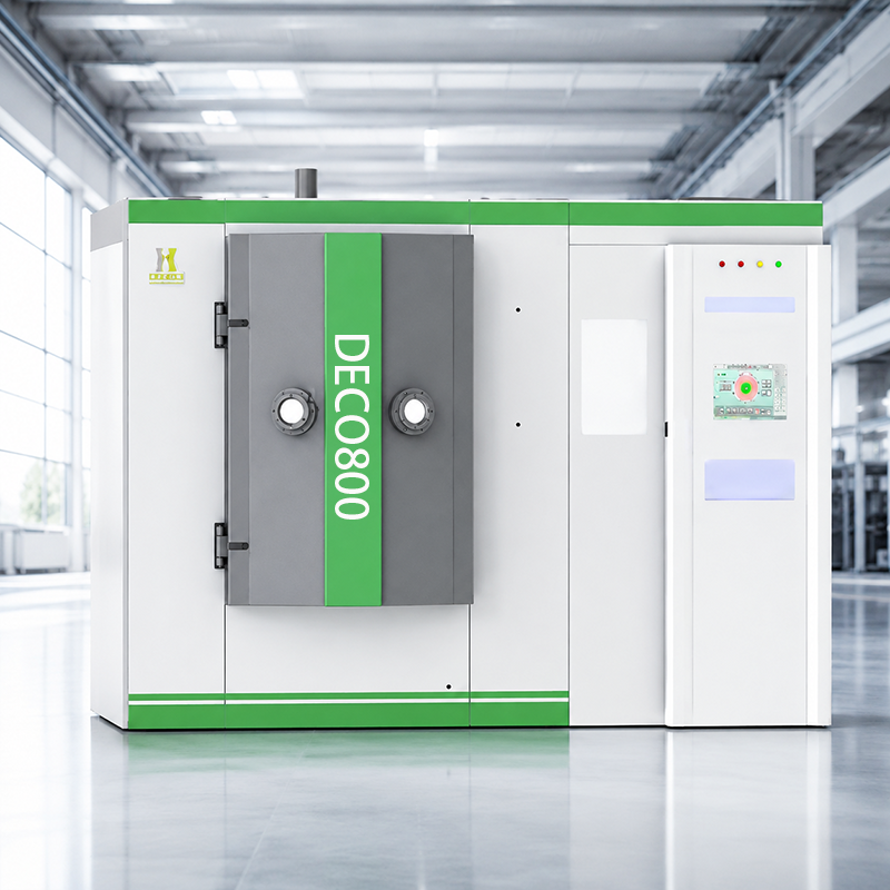
The China TLC Series Anode Layer Ion Source Coating Machine is designed for manufacturers seeking consistent, high-performance thin films. Combining Magnetron Sputtering with an anode layer ion source, it generates a stable, high-current ion beam through a compact cold-cathode structure. This configuration supports ion-beam-assisted deposition, substrate cleaning, and film densification while enabling precise control of ion energy. Industry analyses, including the MarketsandMarkets PVD coatings report, project continued annual growth of approximately 7–8% for the PVD coating sector through 2028, driven by demand for durable, energy-efficient surface treatments.
For suppliers and factories evaluating coating equipment, the TLC series offers improved adhesion, thickness uniformity, and coating density across diverse materials. It is particularly suitable for Diamond-Like Carbon (DLC) films, which are valued for low friction, high hardness, wear resistance, and relatively low internal stress. These properties support applications in automotive components, precision tooling, medical devices, and aerospace parts. Reports from Grand View Research also identify automotive and industrial manufacturing as major contributors to advanced coating demand, reinforcing the need for flexible and scalable deposition platforms.
With efficient process control, adaptable material compatibility, and reduced reliance on complex source structures, the TLC series provides a cost-conscious route to advanced surface engineering. Factory-direct technical support, configurable chamber layouts, and stable production performance make it a practical option for Chinese and international coating suppliers serving demanding industrial markets.
PVD creates a thin film inside a vacuum chamber. Solid material becomes vapor, then condenses on a prepared surface. Typical thickness ranges from 1 to 5 micrometers. Very thin, but useful.
Cleaning, ion bombardment, substrate temperature, and bias voltage strongly affect adhesion. Poor cleaning can ruin an otherwise excellent film. Thickness alone proves little.
Cathodic arc provides strong adhesion and dense films. Magnetron sputtering creates smoother surfaces and better coverage. High-power pulsed sputtering can improve density, but needs careful tuning. No process wins everywhere.
Titanium aluminum nitride can handle high cutting temperatures. Titanium nitride supports moderate wear protection and easy visual inspection. The best choice depends on speed, load, lubrication, and tool hardness.
No. A very hard layer can chip when a forming die flexes or receives impact. A slightly softer coating may survive better. That detail is easy to miss.
Match thickness to edge geometry and surface function. Excessive thickness may affect sharp edges or tight clearances. Check corners, holes, and radii under magnification.
Use microscopy, calotest measurements, or X-ray fluorescence testing for thickness. Test hardness, friction, corrosion resistance, and adhesion. Real production conditions matter more than one laboratory result.
Coverage may become uneven on deep holes, recessed areas, and complex edges. Fixture rotation can help, but it cannot solve every geometry problem. Inspect difficult areas directly.
Medical components need corrosion resistance, cleanability, and surface compatibility. Electronic parts need controlled thickness, uniformity, and electrical behavior. Measure across the complete panel, not one convenient spot.
Do not select a coating from a chart alone. Compare cleaning cycles, temperatures, loads, and real fluids. Early choices may need revision. That is normal.
This guide explains how physical vapor deposition coating systems create thin, highly engineered films, typically 1–5 μm thick, inside a controlled vacuum environment. It reviews major coating families, including TiN, CrN, TiAlN, AlTiN, DLC, and multilayer structures, while comparing their potential benefits in hardness, wear resistance, adhesion, and high-temperature stability. Some advanced formulations can deliver hardness in the 20–40 GPa range and maintain oxidation resistance at temperatures approaching 2,000°C, depending on composition and operating conditions.
The article also compares cathodic arc, magnetron sputtering, and HIPIMS deposition routes, highlighting differences in energy, surface finish, productivity, and coating performance. Practical guidance connects coating selection with cutting tools, forming dies, medical devices, and electronic components. For 2026, the most reliable choice should balance expected wear life, substrate adhesion, service temperature, process capability, maintenance needs, and total cost rather than relying on hardness alone.